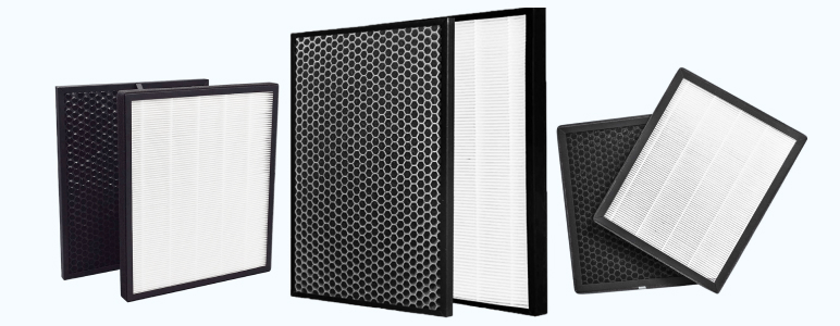


Carbon filter section SUF type
The carbon filter section is designed to clean the air from gaseous, steam (molecular, organic and inorganic) contaminants, as well as odors in exhaust ventilation systems.
How to order
Leave a request and we will contact you to clarify the details of your order and select the necessary equipment.
Technical requirements and characteristics of carbon filter sections (CF)
| Indicator name | Dimension | Magnitude | |||||
|---|---|---|---|---|---|---|---|
| Brand SUF | |||||||
| 0/10 | 0/20 | 0/30 | 0/40 | 0/60 | 0/90 | ||
| Nominal capacity | m3/h | 2500 | 5000 | 7500 | 10000 | 15000 | 22500 |
| Initial aerodynamic drag | Pa | 170 ± 10 | |||||
| Recommended operating parameters, temperature, no more than Humidity, no more than |
0С % |
40 70 |
|||||
| Dimensions, | |||||||
| height | mm | 605 | 605 | 605 | 1166 | 1656 | 1656 |
| width | mm | 582 | 1076 | 1570 | 1112 | 1112 | 1606 |
| depth | mm | 766 | 766 | 766 | 808 | 808 | 808 |
| Weight | kg | 87 | 134 | 199 | 288 | 398 | 554 |
General arrangement of carbon filter sections (CF)
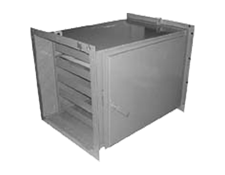
The carbon filter section consists of a metal housing with a flange at the inlet and outlet. The holes in the flanges are intended for connecting the SUF with the corresponding flanges of the ventilation system with bolts through sealing rubber.
The section has a door through which access is provided to the filter elements, which are cells inserted along U-shaped guides into the SUF body and sealed in the body after the door is closed. The filter elements are filled with granular activated carbon. The sealing of a door with a rubber seal glued along its perimeter with the body is carried out by pressing the door to the body using a rotary handle (handles). At the same time, the filter elements in the housing are sealed.
Overall and connecting dimensions of SUF sections, mm
| SUF code | L | L1 | H | H1 | B | t1 | t2 | l | l1 | n | n1 | n2 |
|---|---|---|---|---|---|---|---|---|---|---|---|---|
| 0/10 | 582 | 500 | 605 | 480 | 766 | 250 | 160 | 62.5 | 41 | 28 | 2 | 3 |
| 0/20 | 1076 | 1000 | 605 | 480 | 766 | 250 | 160 | 62.5 | 38 | 36 | 4 | 3 |
| 0/30 | 1570 | 1000 | 605 | 480 | 766 | 250 | 160 | 62.5 | 35 | 44 | 6 | 3 |
| 0/40 | 1112 | 1000 | 1166 | 1035 | 808 | 200 | 207 | 65.5 | 56 | 48 | 5 | 5 |
| 0/60 | 1112 | 1000 | 1656 | 1540 | 808 | 200 | 220 | 58 | 56 | 56 | 5 | 7 |
| 0/90 | 1606 | 1505 | 1656 | 1540 | 808 | 215 | 220 | 58 | 50.5 | 64 | 7 | 7 |
Marking of carbon filter sections (CF)
SUF 0/10P – C-section;
U- coal;
F-filter;
0 – standard size of the section corresponding to the standard size of the FYaK section;
10 – number of filter elements (cells);
R – right version (the door is located on the right side in the direction of air movement);
L – left version (the door is located on the left side in the direction of air movement).
Recommendations for the operation of carbon filter sections (CFS)
As mentioned above, the SUF section is designed to clean the air from gaseous and vapor contaminants that are sorbed by the fine-porous structure of activated carbon. For normal operation of the SUF, a preliminary cleaning of dust and fine aerosols must be installed in front of it to prevent dust contamination of activated carbon granules, which can significantly reduce the sorption capacity of the SUF and, as a consequence, the service life. For this, filters of class no lower than F7 must be used (for example, section pocket filters SKF with filter FyaK class F7). During the entire period of operation, if the above recommendations are followed, the aerodynamic resistance of the SUF remains practically unchanged.
Related products
-
 Purification of ventilation emissions
Electric filters type FEKV
Specify the priceФільтри електричні типу ФЕКВ призначені для очищення повітря від аерозолів твердих та рідких речовин, у тому числі від...
-
 Purification of ventilation emissions
Fiber filters type FKG-T and FKG-N
Specify the priceВолокнисті фільтри ФКГ-Т; ФКГ-Н та ФКГ-П аналоги фільтрів ФВГ-Т та ФВГ-М призначені для санітарного очищення повітря...
-
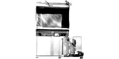 Purification of ventilation emissions
Ion exchange filters type RIF, FK, RIF-FK
Specify the priceІонообмінні фільтри РІФ, ФК, РІФ-ФК призначені для очищення газів від токсичних газоподібних та аерозольних домішок...
-
 Purification of ventilation emissions
FSV type filters for purifying compressed air from aerosol impurities
Specify the priceФільтри для очищення стисненого повітря ФСВ підвищують надійність та термін служби пневматичного обладнання, верстатів...
-
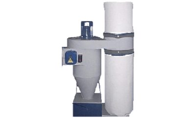 Purification of ventilation emissions
Universal mobile dust collectors
Specify the priceПропонуємо до Вашої уваги нове покоління внутрішньоцехових мобільних пиловловлювачів. Промислові пиловловлювачі В-9,...
-
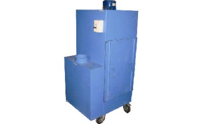 Purification of ventilation emissions
Recirculation dust collection unit type PAR-M
Specify the priceПилоуловлюючий агрегат рециркуляційний ПАР-М призначений для уловлювання дрібнодисперсного пилу при невисоких...
-
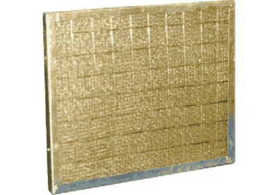 Purification of ventilation emissions
Cell filters type FyaZh
Specify the priceФільтри коміркові типу ФяЖ призначені для очищення витяжного повітря від масляних та жирових аерозолів, що видаляються...
-
 Purification of ventilation emissions
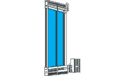
Roll filters type FRS
Specify the priceФільтр рулонний сітчастий (замість фільтрів ФРПМ) призначений для очищення рециркуляційного повітря від волокнистого...
-
 Purification of ventilation emissions
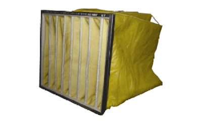
Ion exchange pocket filters type IFK
Specify the priceФільтри типу ІФК призначені для очищення повітря в системах припливної та витяжної вентиляції, а також системах...